
Sub-Total: ₱0.00
Infill density
The infill density defines the amount of plastic used on the inside of the print. A higher infill density means that there is more plastic on the inside of your print, leading to a stronger object. An infill density around 20% is used for models with a visual purpose, higher densities can be used for end-use parts.
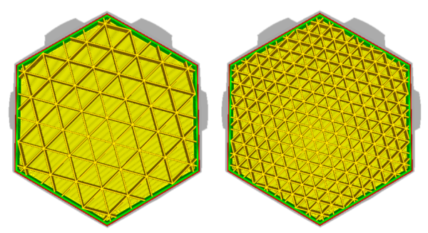
The model on the right has a higher infill density than the model on the left
Infill line distance
Instead of setting the infill density as a percentage, it’s also possible to set the line distance. This determines the distance between each infill line, which has the same effect as changing the infill density.
Infill pattern
Ultimaker Cura allows you to change the pattern of the printed infill structure, which is beneficial in some use cases. For example:
- Strong 2D infills are used for everyday prints
- Quick 2D infills are used for quick, but weak models
- 3D infills are used to make the object equally strong in all directions
- 3D concentric infills are used for flexible materials
The following pattern options are available:
- Grid: Strong 2D infill
- Lines: Quick 2D infill
- Triangles: Strong 2D infill
- Tri-hexagon: Strong 2D infill
- Cubic: Strong 3D infill
- Cubic (subdivision): Strong 3D infill (this saves material compared to Cubic)
- Octet: Strong 3D infill
- Quarter cubic: Strong 3D infill
- Concentric: Flexible 3D infill
- Zig-zag: A grid shaped infill, printing continuously in one diagonal direction
- Cross: Flexible 3D infill
- Cross 3D: Flexible 3D infill
- Gyroid infill: Infill with increased strength for the lowest weight.
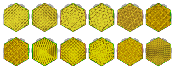
The infill patterns are displayed in the order of the list above, from left to right.
Infill line directions
The infill lines usually print at a 45° angle. At this angle, both the X- and Y-motor work together to obtain maximum acceleration and jerk on the layer without losing quality. If the lines need to be printed in a different direction, you can set it here at 0° for vertical and 90° for horizontal. For example: [0,90] results in a horizontal-vertical top/bottom pattern.
Infill XY offset
Infill patterns are centered for each model loaded. To move the pattern to the left, right, top, or bottom a X or Y offset can be used. A positive value moves it UP and RIGHT, while a negative value moves it DOWN or LEFT. This does not work for the concentric infill types.
Infill overlap percentage
With this setting you can control the amount of overlap between the infill and walls. It can be set as a percentage or a true value. A higher value usually results in better bonding between the infill and walls. However, it might also reduce the visual quality of the print, as a value that is too high could lead to over extrusion. The default value in Ultimaker Cura will in be sufficient in most cases.
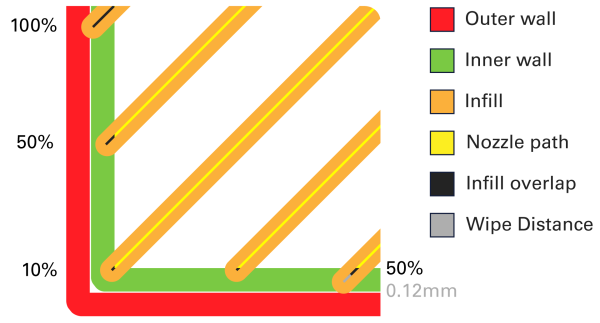
A visualization of the infill overlap and wipe distance
Skin overlap (percentage)
The skin overlap works in the same way as the infill overlap, which is described in detail above. It can be set as a percentage or a true value. The skin overlap influences all top and bottom layers in a print.
Infill wipe distance
This setting instructs the printer to stop extruding at the end of printing the infill before it starts printing the walls. The printer will still ooze a little bit of filament due to the pressure in the nozzle, but by stopping the extrusion early, you’ll reduce over extrusion on the shell. See the image above.
Infill layer thickness
Since the layer height of the infill is not important for visual quality, you can use thicker layers on the infill to reduce the print time. When adjusting this setting, always make sure that it is a multiple of the layer height, otherwise Ultimaker Cura will round it up to a multiple of the layer height. This means that you can, for example, print with an infill thickness of 0.2 mm while the layer height is 0.1 mm. The printer will first print the walls for two layers, and then it will print one thicker infill layer.
Gradual infill steps
Gradual infill reduces the amount of infill used by decreasing the infill percentage in the lower layers. Every gradual infill step divides the infill percentage by a factor two. The result is a dense infill near the top layers, which is essential, and a reduced print time.
Example: Gradual infill steps = 2 and infill = 20% –> Infill = 20% for the top 5mm, infill = 10% for the rest of the print
Gradual infill step height
Gradual infill step height is the height at which the infill should be reduced, as calculated from the top layers. This way the top layers can easily be closed, without the use of extra infill in the print.
Infill before walls
With this setting enabled, infill will be printed before the walls. This results in better overhangs because the walls will stick to the already printed infill. Printing in this order can also have a disadvantage. If the infill is printed before the walls, there is a chance that the infill will be visible through the walls, resulting in a rougher surface finish.
Minimum infill area
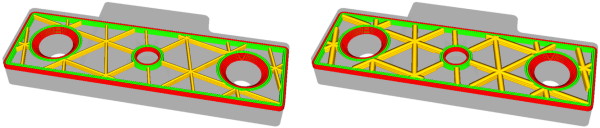
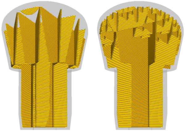
This setting allows small areas on a single layer to be printed with skin instead of infill. Take a flat roof with a chimney, for example, the chimney is thin and fragile and can be printed solidly with skin.
The minimum infill area strengthens the legs of this coupler by filling it completely with skin
Skin removal and skin expansion
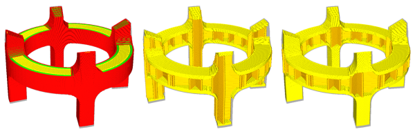
The skin (top and bottom layers) in a model is printed to reach the minimum thickness set in the print profile. However, some models need a stronger or lighter internal geometry. These settings expand or remove the skin horizontally, where infill would normally be printed. Expanding this slightly allows protruding model elements to have better adhesion to the rest of the model, making it stronger or lighter. Flat surfaces with protruding elements in the Z-direction will have a stronger base, making it sturdier.
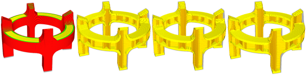
From left to right; A preview of the model, skin expansion of 0.8mm, no skin expansion or removal, skin removal of 0.8mm
Skin removal width
This is the width of the skin to be removed when applying skin removal. It can be applied individually to the top and bottom layers.
Skin expand distance
This refers to the distance by which the skin will be expanded. A bigger value results in longer, but sturdier prints. A lower value will only marginally increase the strength.
Maximum skin angle for expansion
Since skin is present throughout the model, it is unnecessary to expand all of the areas. Rather, only the areas below the angle specified here will be expanded. In that way, flat surfaces with protruding elements will be strengthened, without affecting the rest of the model. For this, 0° is horizontal (and does not expand anything), while 90° is vertical, and expands everything.
Minimum skin width for expansion
This parameter will prevent small skin (top and bottom) areas from expanding. It is specifically used when targeting only the strength of large, flat surfaces of the model.
Original composition by : Ultimaker (https://support.ultimaker.com/hc/en-us/articles/360012607079-Infill-settings)
Posted in Guides